When Honda built the first generation Insight, Automotive battery technology was in its infancy. When the Honda engineers were tasked of building the energy storage for the hybrid system of the Insight ZE1, the new Nickel-Metal-Hydride cell types were cutting edge technology. In fact, only one year before the ZE1 was released, General Motors switched from Lead-Acid to NiMH in their EV1 electric car.
The Quirks of Nickel Metal Hydride Battery Technology
For Honda engineers, the NiMH technology was incredibly new, and posed many additional challenges compare to the easier-to-use lead acid batteries.
Similar to modern-day Li-Ion cells, NiMH cells require constant monitoring to avoid overcharging or -discharging. Additionally, charging NiMH is very complex, and in fact more difficult to handle than the newer Li-Ion technology. Besides the usual capacity and state of charge (SoC) computation, NiMH monitoring systems have to deal with NiMH specific quirks, such as voltage depression, reverse charging and memory effect.
In retrospective, Honda engineers did a surprisingly good job – for the time – when designing the battery monitoring system (BMS) of the ZE1. It works well in most cases and works very well with brand-new cells it was designed for (Panasonic), but once cells start aging or different cells are used, it starts to fail in many different ways.
How the BMS monitors Cell Voltages and Temperatures
To better understand the flaws of it, let us have a closer look how the BMS monitors the cells of the 144V battery pack. The pack consists of 120 cells, each with 1.2V nominal voltage. The cells are organized in sticks, with each stick consisting of six cells welded together.

To avoid overheating, overcharging and overdischarging, the sticks are monitored using three mechanisms:
- voltage probes are connected to every 12th cell, measuring in total 10 voltages.
- 120 PTC elements are wired in series, one for each cell. If a cell overheats, the resistance of the PTC element rises, and the BMS is aware of a cell overheating.
- Four additional temperature probes measure the temperature within the battery at different locations. Unlike the PTC probes, they give a precise reading of the battery temperature.
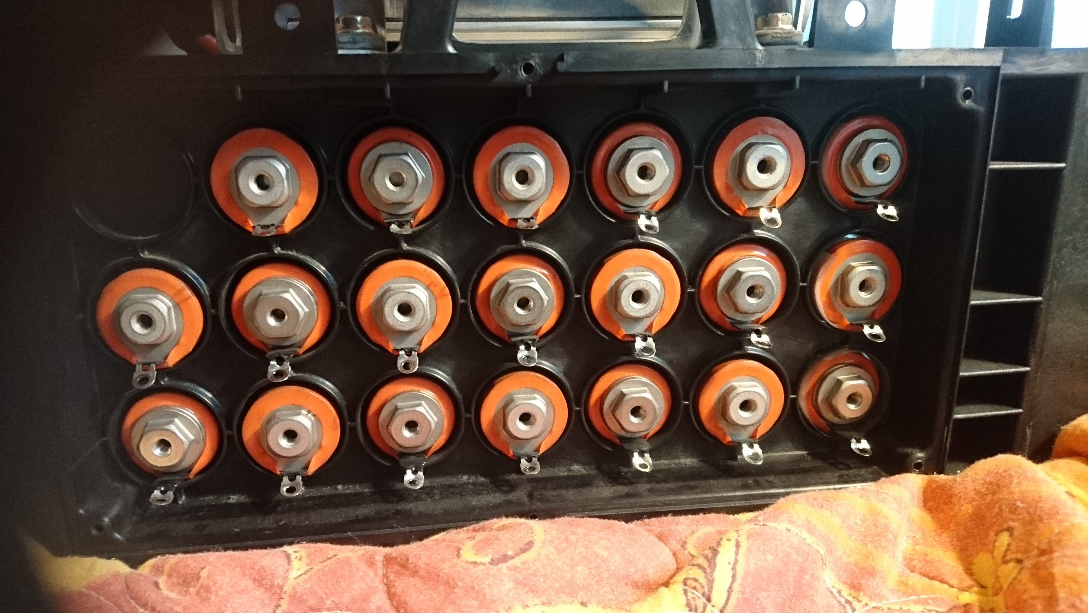
The connection points for these probes are shown below.

Let’s take a closer look at a pair of battery sticks. As explained above, a voltage probe is connected at every 12th cell (two sticks), giving in total 10 delta voltage readings. The BMS always monitors two sticks connected in series. Below pictures shows how two sticks are monitored together.

With that information, the BMS is able to detect the following conditions:
- if any cell is discharged to 0% (“dropout” when a cell voltage drops to 0).
- overcharge if the cell temperature rises due to excessive energy transformed into heat.
- Overall battery pack balance can be estimated by comparing the off-load voltage and the voltage drop under load across the 10 stick pairs.
This monitoring is quite good; and while it doesn’t tell you which exact cell is causing the problem, it allows for reliable identification of degraded battery states.
Voltage Monitoring
By monitoring the voltage of each pair of sticks, the BMS is reliably able to identify a “cell dropout”, i.e. a cell being fully discharged, while others are still charging. To explain this better, let us start by looking at a “healthy” battery, where all cells have the same capacity, and are charged to the same level (70% in this example).

If you discharge such a battery, the voltage curve during discharge would look somewhat like that. At some point, all cells will be empty, and the total voltage will drop to 0.

Looking at the cell-level SoC, all cells should have fully discharged by now.

Over-discharge Protection
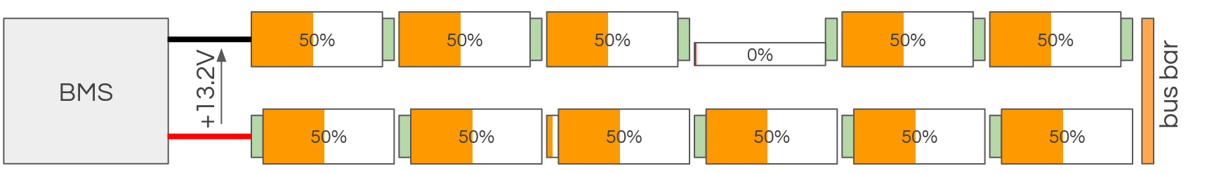
Let’s change the scenario, and assume that the cells are slightly different. Either one of the cells has lost capacity due to aging, or is discharged further than the rest of the pack. The pack is out of balance.

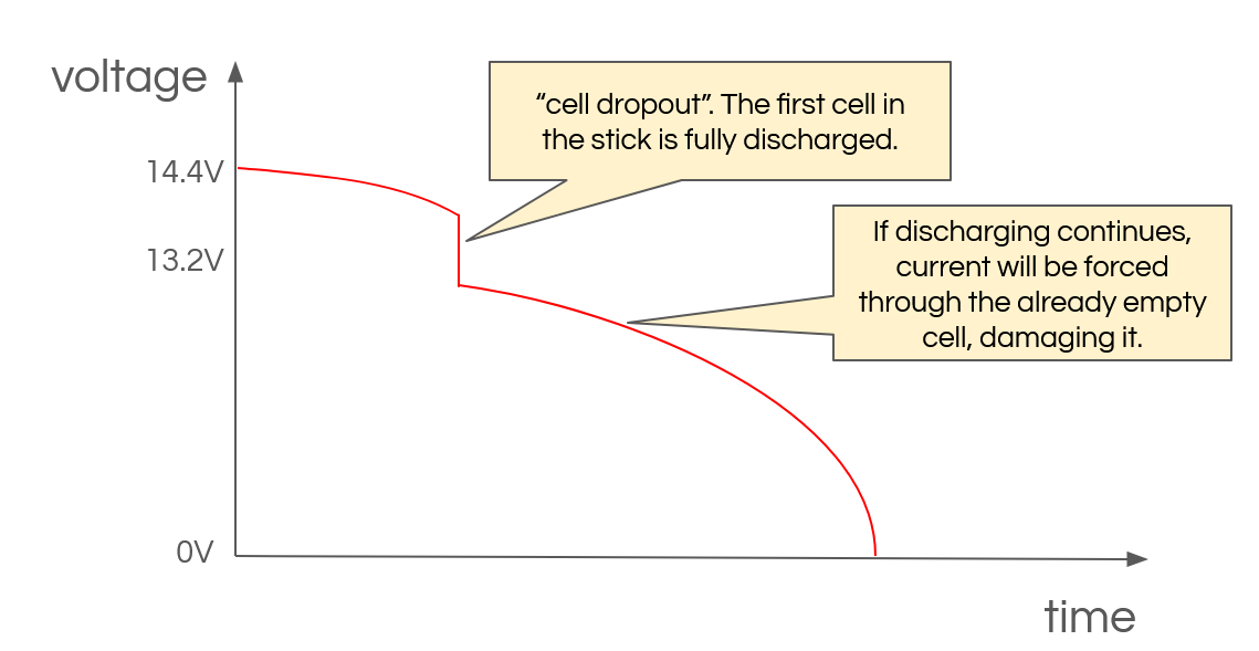
During discharging, the cell with the initial charge of 30% will be fully discharged first, and at some point reach 0% charge. The cell voltage drops to 0V – the cell drops out.

The discharge curve would look something like below: a sudden voltage drop is seen when a cell drops out. If discharging of the pack continues, the voltage from the other cells force current through the already fully discharged cell, causing a negative voltage within the cell. This is called “reverse charging”, and will damage the cell.
To maximize battery life, the BMS must avoid reverse charging at all costs. The Honda Insight ZE1 BMS does so by monitoring the stick pair voltages and looking for potential cell dropouts. If a cell drops out, discharging (assist) is stopped, even if the remaining 119 cells could still provide charge. Therefore, a single bad cell limits the capacity of the entire pack.
The BMS reacts to this situation by doing a “negative recalibration”. It resets the overall battery pack SoC to 0%, and starts aggressively charging the pack. The SoC now matches the charge state of the weakest cell (calibrated). A careful driver can observe such a negative recalibration when the battery SoC display on the instrument cluster slowly drops to 0 bars, no assist is available, and the car enforces aggressive charging. By doing so, the BMS has an effective method to prevent overdischarging a cell.
Overcharge Protection
Overdischarging a battery is bad. Few people know that overcharging is similarly bad. Unfortunately, there is no easy way to identify if a NiMH battery cell is overcharged. Looking at the charge curve of a NiMH cell, the cell voltage plateaus at some point during the charging. By monitoring at the voltage alone, there is no way to identify if the battery is being overcharged.
A NiMH cell that is overcharged will start burning off the excessive energy in heat. If overcharged excessively, hydrogen will build up in the cell, and the cell may vent (if it has a safety valve) or pop (cheap cells without safety valve).

The Insights BMS identifies cell overcharge primarily by voltage and cell temperature monitoring. If the total cell voltage raises too high during charging, or the battery pack temperature raises significantly during charging, the BMS assumes the battery is fully charged, and resets the pack SoC to 80%, stopping all charging (positive recalibration).
As a driver, you can identify such a positive recalibration if the SoC gauge on the instrument cluster jumps to fully charged within a few seconds.
I haven’t identified the exact conditions under which the BMS identifies overcharge, but it is likely related to temperature and voltage. I observed that positive recalibrations can happen with the car turned off, for example when recharging on a downhill slope, and then parking the car immediately afterwards. If the BMS registers a rising battery temperature even if the car is turned off, it concludes that the charge from driving it a while ago has fully charged the cells, and the rise in cell temperature is caused by excessive energy being transformed into heat.
Any overcharge event causes damage to the cells. If the BMS is not yet aware that the battery is fully charged, because the rising temperature has not yet been registered, and you hit the brakes, applying full regen, you will force 30-80A into an already fully charged battery.

Even at minimum background charge, the Insight charges with at least 3-4A, which is high enough to cause cell damage. Therefore, if you want to balance your cells, you need to do it with a slow-charging grid charger, that uses at most 0.1A, where the likelihood of cell damage is much less.
The Battery-Capacity is Hard-Coded in the BMS
The main issue with the ZE1 BMS system is that it uses a hard-coded battery capacity. It is not able to handle battery capacity degradation, and always assumes that the battery sticks of the ZE1 provide 6.5Ah.
If a cell has full (factory) capacity of 6.5Ah, the BMS will do a good job at keeping the SoC between 25% and 70%, never overcharging or over-discharging it: it works by counting the coulombs that entered (charging) or left (discharging) the battery so compute the SoC.
However, that state of charge always assumes a capacity of 6.5Ah. If the capacity drops due to aging, the SoC computation will not be correct. Assuming that the cell lost 30% of its capacity, then by the time the BMS has calculated a 70% of charge, the actual cell has reached 100% of the capacity, bringing it dangerously close to overcharging. If the cell capacity drops even further, the car will enter an infinite cycle of positive and negative recalibrations, accelerating damage to the already weak cell.
Why is this a Problem?
Assume a cell capacity has degraded to 50% of its capacity. Imagine you take one of the D cells out of the stick, and replace it by a smaller AA cell. It has exactly the same effect as a degraded cell.
Luckily, you are a responsible Insight owner, and have recently grid-charged the back, balancing all cells to 100%. The BMS also recognizes that the battery has been fully charged, and resets the SoC to 80%.

Now, you start driving, and the hybrid system assist will start discharging the battery. At some point, the weak cell will be fully discharged. Let’s assume you have discharged 50% of the rated capacity, so the actual cell SoC for the “good” cells dropped to 50%, the “bad” cell dropped to 0%. The BMS overall SoC will be 30% (= 80% – 50%).
The BMS will identify a cell dropout, and assumes the pack is empty. It resets the overall SoC to 0%, and starts aggressive charging (negative recalibration).
With the SoC being set to 0%, the car will now charge, trying to bring the BMS SoC to 70%. Because the BMS has a hard-coded cell capacity, it can not understand that the capacity is degraded, and will keep charging until the weak cell is fully charged again.

Cells that are empty are easier to accept charge than cells that are only halfway discharged. The smaller capacity cell will reach 100% first, roughly when the BMS SoC has reached 50%. It will start overcharging the weak cell, until it heats up, at which point the BMS resets the capacity to 80% (positive recalibration). The cycle will now start again. By using assist, the pack discharges until the degraded cell drops out again.

If this happens a few times, the healthy cells will settle at a SoC that matches the BMS SoC, but the weak cell will go from overdischarge to overcharge, back and forth. Note that the BMS is designed to keep the SoC of each cell in a healthy SoC range of 25-70%, but in this case, it fails miserably.
How the BMS Should Behave
Today, even the cheapest notebook battery has a mechanism to cope with cell degradation. They differentiate between nominal and actual capacity. That is why even if your notebook battery only lasts 10 minutes, the battery indication (SoC) is still more or less accurate.
The Insights ZE1 BMS doesn’t have that ability. For some reasons, the BMS software doesn’t support battery degradation, causing the frequent recalibrations. Interestingly, I noticed when reverse engineering the CAN bus of a Honda CR-Z, that the CR-Z BMS displays the same behavior, but due to the few bars for the SoC display on the cluster, it is much less visible.
Should the BMS have a method to “learn” the actual battery capacity? I think so, but it seems to be quite difficult to implement. You would need to consider the possibility that the cells have been replaced, and how about temporary degradation due to voltage depression, or sitting idle for a long time? Notebook battery BMS only need to consider a single set of cell lives, so they write the actual capacity in their EEPROM, and never go higher than that. A notebook discharges an almost constant current, making it much easier to detect overcharge and discharge. A car can’t do that, because the cells may be replaced as part of maintenance, the driving profiles differ, and every driver has its own individual driving style. A car is simply more than just a notebook on wheels.

Surprisingly, even with the simple software the BMS is built with, is works surprisingly well to make the battery last several years. I don’t think the design flaws of the BMS were intentional. Honda was still learning brand-new technology, and there are several design decisions to make the BMS a robust system that can handle a variety of scenarios, and did so very successfully. My intention with this article is to share the technical details I learned by driving and reverse-engineering my Honda, and by observing the little quirks it has.
Overall, I love my Insight, and I am very grateful to Honda and the engineers that made it possible for us to drive this car, and own it up to this day. Even in 2024, there is not a single affordable car that is similar to the ZE1, with such an outstanding fuel economy combined with driving pleasure.